Electricians usually swap a new starting capacitor if an A/C electric motor cannot start properly. It is the easiest and cheapest way to fix the problem. You need to know the AC capacitor wiring colors – a full guide to do this.
Follow the color-coding of its wires to replace a capacitor properly. For example, the basic wiring color system in a typical fan or blower assembly consists of three colors: red for the positive side of the power source, yellow for the fan motor that controls the speed or rpm, and white, which is the neutral side of the power source, that an electrician should connect to the ground.
In the language of electrical electronics, a capacitor is a component that stores electrical energy in an electric field. As such, it is a passive device. And like all electrical devices, it also has two terminals. Capacitance refers to the effect of capacitors.
Read on to learn more about AC capacitor wiring colors, how a capacitor works, and how it is usually wired or connected to an AC electric circuit.
AC Capacitor Wiring Colors – Full Guide
Used in a Typical AC Electric Circuit
A capacitor is in a typical AC electric circuit that powers an electric motor. An electrician usually checks the capacitor’s status when an electrical motor fails to start. In replacing a capacitor, you need to follow its color-coding system to ensure that you won’t connect the wires by mistake.
Wiring Colors
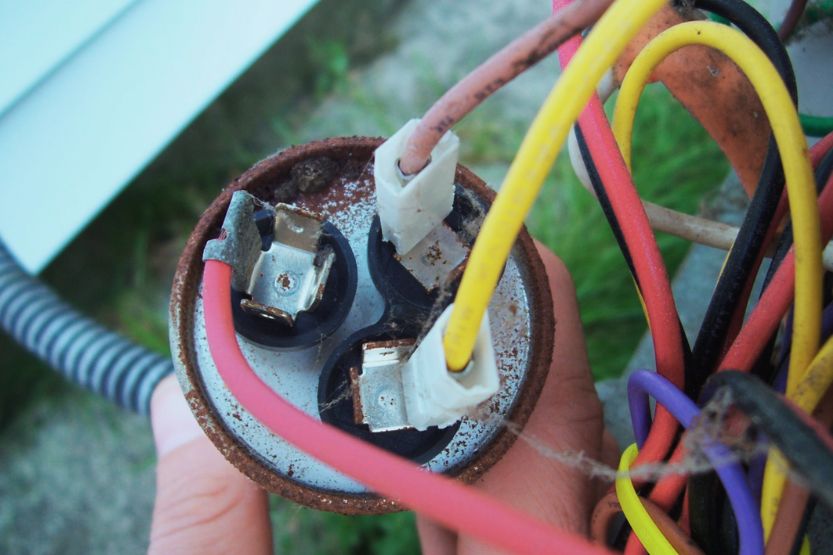
Three wiring colors are in a blower or fan assembly’s basic wiring system. The first color is red, representing the power source’s positive side.
A yellow wire controls the fan motor’s speed or rpm. The last color is white, representing the circuit’s neutral side, which an electrician connects to the ground.
A Capacitor Is a Device That Stores Electrical Energy
In the language of electricity, the capacitor is the device that stores electrical energy in an electric field. A capacitor contains several plates that store electrical charge when connected to a voltage or power source. As such, a capacitor acts as a passive electrical device.
Capacitors Have Two Terminals
Capacitors, just like any other electrical component, come with two terminals. Capacitance refers to the effect that they produce in an electrical circuit.
For example, in electrolytic capacitors, there are always two terminals. One terminal is the anode or the positive pin, while the other is the cathode or the negative pin. The anode of capacitors connects to the circuit’s higher voltage.
Dual Run Capacitors Have Three Terminals
Heat, Ventilation, and Air conditioning Systems (HVAC) have dual-run capacitors. Unlike ordinary capacitors with only two terminals, dual-run capacitors have three. But in terms of operation, they work like ordinary run capacitors with just two terminals.
What Is a Capacitor
Important in the Efficient Operation of Big Electric Motors in HVAC Systems
Capacitors are important in efficiently operating big electric motors used in HVAC systems. For instance, the compressor motor of an air conditioning system has a high starting torque. It uses a start capacitor kit to help start the motor.
Start Capacitor Kit Inclusion
The typical start capacitor kit consists of a start capacitor, a set of wires, and a relay. This capacitor provides the electrical windings of the electric motor a needed boost during the start-up phase.
Once the electric motor starts running and has enough speed, the relay disconnects the capacitor from the electrical circuit being used by the electric motor.
Wires Are Designed Using a Color Code
The wires inside a start capacitor kit have a color code.
They have insulations that distinguish them from one another. Electricians also use this code to connect to the motor’s run capacitor and a contactor.
Generally, all electricians use common capacitor wire colors as the standard.
Actual Wire Colors Vary Depending on Several Factors
However, in practice, the actual correct wire colors used to match fan motor terminals, capacitor terminals, and wires may vary depending on the brand of the motor, the application, and the age.
Even then, electricians usually follow certain steps that help them sort out where the wires ought to go. So, if an electrician forgets to mark the wires that he has already cut off from their former connections, they can still re-connect them correctly to the newly installed capacitors.
How to Distinguish Capacitor Wires

There are times when electricians forget to mark the wires that they disconnect from the capacitor terminals. So, if there’s a brown, yellow, black, and blue wire, what do they do? Even those who have said their pieces on HVAC online chats and forums have different opinions about this matter.
You could spend hours reading comments from forums about start-run capacitor wiring, and it will still be unclear what is the right guide to capacitor color wiring codes.
The main reason for this is that electricians are hesitant to give an answer that has the potential to burn up equipment or maybe even kill someone.
A Technician Uses an Insulated Screwdriver to Short the F and H Terminals
In real-life practice, the electrical technician usually uses an insulated screwdriver to short the F and H terminals connected to the COM terminal so they can discharge the capacitor. Why do they need to discharge the cap?
If the stored power in the capacitor is still large, you should not touch it at all. Accidentally touching live voltage can kill. The safest way is to turn off the power and discharge the stored power inside the capacitor before you try to touch anything in the circuit.
So, this work requires proper training to handle electricity and electrical components.
Practice Tagging Every Wire
The lesson here is: that it is best to practice tagging every wire. Give each wire an ID and write where each wire is connected to before disconnecting them from their electrical connections. You also need to refer to the diagram that should be attached to the electrical equipment itself.
Run Simple Volt-Ohm-Milliammeter (VOM) Tests
Follow the marked terminals on its start or run capacitor. If you have a multimeter, you can also run simple Volt-Ohm-Milliammeter (VOM) tests to check and identify the terminals of the electric motor and capacitor.
Check the HVAC Equipment’s Wiring Diagram
Checking the wiring diagram of your HVAC equipment may give you the location of the capacitor. Follow the wires and identify them.
Usually, you can find a wiring diagram inside the HVAC equipment’s air handler cabinet. If it’s not there, it could be inside the blower compartment door.
When you’ve looked everywhere, and you can’t find any diagram, your last resort is to contact the manufacturer of the HVAC equipment and ask them for a copy.
How to Find Start or Run Capacitor Wirings Using a Wiring Diagram
If you already have the diagram, here’s how you will find the start or run capacitor wirings:
- Check the data tag of the blower fan motor. It should provide the terminal identifications of the wirings.
- If you have a multi-speed motor, use a VOM multimeter to measure the resistance between the speed and common wire from the motor. If the resistance is higher, the motor’s rotational speed is lower.
- An electrical technician will trace the wires from their loose end back to the source so that they can match the normal connections given in the diagram.
- If the markings are unclear, the electrical tech will test the motor to identify the different terminals.
There may be extra wires or wires not used in blower fan motors. Their use depends on the required fan speeds. Electrical techs follow these principles to identify these wires:
- In simple cases – a single-speed motor will have the fewest wires. Usually, there will only be three wires, one for a start, another for a run, and the third one for common.
- In more complex cases – a motor with 2 or 3 speeds (low, medium, high), 2 or 3 wires are added to the three wires of simple motors.
- In more complex cases – for a motor that can run clockwise or counterclockwise, 2 to 4 wires are added to the usual three wires of simple motors.
How to Wire Up a Start-Run Capacitor
You already know that start-run capacitors come with color-coded insulations. Their wires connect to the electric motor’s run capacitor and a relay or contactor that supplies electricity to the motor. The steps in wiring a capacitor for this kind of motor are as follows:
1. Turn Off the Motor
The first thing you need to do is turn off the motor to cut off its electricity supply. Unplug the motor if connected to the wall outlet, or turn off the motor’s circuit breaker.
2. Check the Wiring Diagram
Examine the wiring diagram of the start run capacitor. This diagram should provide the capacitor’s identity, the relay wire’s color, and the wire’s function. Usually, you will see a stamp on the side of the relay showing the wiring diagram.
3. Push the Common (Black) Wire Terminal
The relay of the start capacitor has a terminal with the tag “Common.” This common wire is usually black. Push it to the common terminal on the load side of the contactor of the motor.
Be aware that there are other wires connected to the common terminal, which are labeled “C” or “COM” on the wiring chart of the electric motor.
4. Push the Run Wire Terminal of the Relay
There is also a wire terminal on the relay of the start capacitor marked “Run.” Push this terminal onto the “HERM” terminal of the run capacitor.
There are other wires connected to this start terminal of the electric motor, which is labeled “S.” These wires also connect to the terminal of the run capacitor of the electric motor.
5. Push One Wire Terminal of the Start Capacitor Kit
The start capacitor kit has wire terminals on each of the short wires. Push one of these wires onto the terminal of the start capacitor. One wire should go on each terminal of the start capacitor.
6. Push the Terminal of One of the Wires of the Start Capacitor
The start capacitor has several wires. Push the terminal of one of those wires onto the “Start” terminal of the start capacitor relay.
7. Push the Terminal on the Second Wire of the Start Capacitor Kit
The start capacitor has another wire. Push the terminal of this second wire onto the common terminal of the start run capacitor with the label “C” or “COM.”
There are other wires connected to this “C” terminal. One of the wires goes to the hot terminal on the load side of the relay or contractor, and the other wire is connected to the run terminal of the motor, labeled “R.”
Again, what color wires go on the AC capacitor? AC capacitors usually have red, yellow, and white wires. The yellow wire controls the fan’s speed, while the white is a neutral wire connected to the ground.
What Are Dual Run Capacitors?
Types of Capacitors Common in HVAC Systems
Dual run capacitors are the types of capacitors common in HVAC systems. These capacitors have three terminals compared to just two terminals of standard capacitors. They are the same as standard capacitors, but only with an additional terminal.
Dual Capacitors Have Three Terminals
What’s the reason for the additional terminal? Dual capacitors, having three terminals, allow the user to save space if the available mounting space is very small. Manufacturers label their terminals clearly. So they are very easy to hook up to the different parts of the air conditioner.
Wiring Connection Label
The wiring connections of dual capacitors are usually labeled “C” for common, “HERM” or “H” for the hermetic compressor, and “FAN” or “F” for the fan used in the HVAC equipment.
These capacitors have usual ratings ranging from 370 to 440 volts. Most of them have 50 Hz or 60 Hz.
Old AC Comes with Two Separate Capacitors
A typical outdoor air conditioner comes with a fan and a compressor. Both these HVAC components require a capacitor for them to operate efficiently. In the past, HVACs used two separate capacitors, one for the fan and another for the compressor.
Modern ACs Have Dual Run Capacitors
Nowadays, modern air conditioners only come with one single capacitor. This capacitor starts and runs both the fan and the compressor. This capacitor is the dual-run capacitor.
As I’ve already mentioned, these capacitors have three terminals. One is for the “C” or common, another is for the “F” or fan, and the third one is for the “H” or “HERM” or hermetic compressor.
Dual Capacitor Wiring Diagram
To help you better understand the wire connection of a dual capacitor, check the AC dual capacitor wiring diagram below:

How to Connect a Dual Capacitor to an AC Unit
The typical method of connecting the dual run capacitor as part of HVAC systems is as follows:
- The common terminal of the dual capacitor should have a connection to the running terminal of the compressor and the fan, as illustrated in the above wiring diagram.
- Connect the dual capacitor’s fan terminal to the fan’s starting terminal.
- The HERM terminal of the dual capacitor should have a connection to the starting terminal of the compressor.
Dual-run Capacitor Terminals
Most dual-run capacitors have terminals in the form of four 1/4-inch push-on tabs. Most of these capacitors have three to four tabs. This gives electricians enough tabs for each connection, so it won’t be hard for them to make the necessary wiring connections.
Terminal Colors
Generally, one terminal for each starting and running electrical wire winding is connected inside and brought outside a terminal designated as the common terminal. Black is the standard color for this terminal.
Two other terminals are brought outside the starting and running electrical wire winding. Blue is the typical designated color used for the starting terminal, while red is the usually assigned color for the running terminal.
These color designations of terminals (and wiring insulation) may vary from country to country. So, you are advised to make sure it is the running or the starting terminal by using a multimeter to measure the resistance across each terminal.
Frequently Asked Questions

This topic is a bit technical so you will have many questions in your mind. Perhaps the answers to your questions are in the list below:
What Are the Wire Colors of a Capacitor?
In general, three colors designate capacitor wires. One of the colors is red, representing the hotline or the power source.
Yellow represents the wire used for the fan motor, which determines the speed of the motor. White means a grounded wire, which is the neutral side of the power source.
How Do You Connect Wires to a Capacitor?
You must follow a set procedure when connecting wires to a capacitor. Usually, the process goes this way:
- Turn off the motor
- Consult the wiring diagram
- Push the common wire (black) terminal and insert the wire (black)
- Push the run wire terminal and insert the run wire
- Push one of the wire terminals of the start capacitor kit and insert the wire
- Push the other wire terminal of the start capacitor kit and insert the wire
- Push the terminal on the second wire of the start capacitor kit and insert the wire.
What Will Happen If a Capacitor Is Incorrectly Wired?
If the wires going to and from the capacitor in an HVAC system are improperly connected, there will be catastrophic results. An explosion or a fire can occur. Installed polarized capacitors will first emit a whistling sound, then explode.
In Closing: Full Guide on AC Capacitor Wiring Colors
You should always follow the color-coding of the wires to connect an AC capacitor properly.
For example, the basic system in AC capacitor wiring uses the following:
- Red for the positive side of the power source,
- Yellow for the speed control of the fan motor, and
- White for the neutral side of the power source; this has a connection to the ground.
Capacitors store large amounts of voltage. They boost the starting power of electric motors and compressors in HVAC systems. If they are incorrectly wired or installed, dire results can happen. So, extreme care should be observed when wiring and installing AC capacitors.